

AVL Tree
Introduction to AVL Tree :
AVL trees are a self-balancing binary search tree data structure that helps maintain the height balance of the tree. They were named after their inventors, Adelson-Velsky and Landis, and are particularly useful for optimising search, insertion, and deletion operations. In this guide, we’ll explore AVL trees, provide an illustrative example, and delve into the step-by-step procedures for insertion and balancing.
Definitions :
Balancing Factor : In AVL Tree Balancing factor of a node means difference in between height of left subtree and right subtree i.e. balancing factor = HL (height of left subtree) – HR(height of right subtree). As a rule of AVL tree this balancing factor of a node must be within a range [ -1 , 1 ].
Affected node : In AVL Tree If The node does not have a balancing factor within the allowed range then the node will be called affected node i.e. the node is imbalanced and needs to have treatment to become balanced. Sometimes it’s also called a critical node.
Relations :
In AVL Tree For determining rotations we need to confirm the relation between the affected node and the node for which it has become affected means just inserted node.
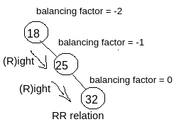
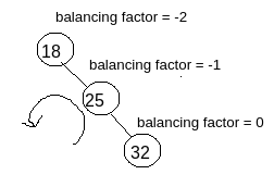
RR Relation : As per the example shown in the image you can see the node with value 18 is affected (because balancing factor is -2) and it has become affected due to the newly inserted node with value 32. So we have to determine the relation (means traversal relation) with the affected node and the newly inserted node.
So, for reaching from the affected node with the value 18 to the newly inserted node with value 32 (for which 18 has become affected) , we have to follow Right traversal then another Right traversal i.e. RR. So as per the image you can see this is RR relation.
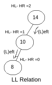
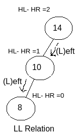
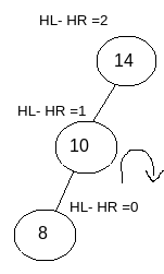
LL Relation : As per the example shown in the image you can see the node with value 14 is affected (because balancing factor is 2) and it has become affected due to the newly inserted node with value 8. So we have to determine the relation (means traversal relation) with the affected node and the newly inserted node.
So, for reaching from the affected node with the value 14 to the newly inserted node with value 8 (for which 14 has become affected), we have to follow Left traversal then another Left traversal i.e. LL. So as per the image you can see this is LL relation.
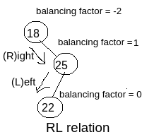
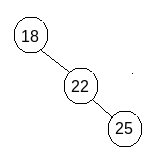
RL Relation : As per the example shown in the image you can see the node with value 18 is affected (because balancing factor is -2) and it has become affected due to the newly inserted node with value 22. So we have to determine the relation (means traversal relation) with the affected node and the newly inserted node.
So, for reaching from the affected node with the value 18 to the newly inserted node with value 22 (for which 18 has become affected), we have to follow Right traversal then Left traversal i.e. RL. So as per the image you can see this is RL relation.
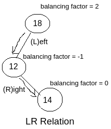
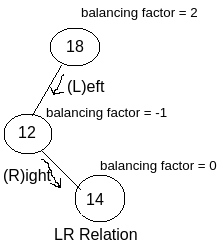
LR Relation : As per the example shown in the image you can see the node with value 18 is affected (because balancing factor is -2) and it has become affected due to the newly inserted node with value 14. So we have to determine the relation (means traversal relation) with the affected node and the newly inserted node.
So, for reaching from the affected node with the value 18 to the newly inserted node with value 14 (for which 18 has become affected), we have to follow Left traversal then Right traversal i.e. LR. So as per the image you can see this is LR relation.
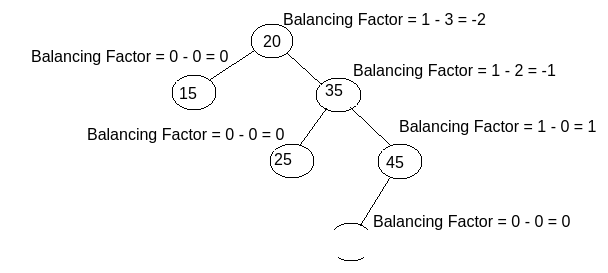
N.B : In some examples it might happen that you need to traverse more steps to reach the just inserted node, for which the tree has become imbalanced. In that case we should consider the first 2 steps. Eg. as you can see in the image the node with value 20 has become affected for the just inserted node with value 40. Now for determining the relation you need to first traverse Right, then Right, and at last Left from the affected node to the just inserted node for which the node has become affected. But here we will consider only first two steps means Right – Right. So the relation will be RR and you have to take solution as per the rule.
Rotations :
Rotation for the relation RR : For RR relation we need to perform Complete Left Rotation with respect to the affected node.
As you can see in the image, RR relation is found so we need to perform Left Rotation with respect to the affected node for giving the solution.
So left rotation need to be performed as shown in the image.
After performing Left Rotation the tree will look like the tree shown in the image. As you can see after performing the Left Rotation , Balancing factor of all the nodes have become proper ( as per the AVL Tree Balancing Rule.).
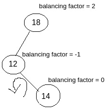
Rotation for the relation LL : For LL relation we need to perform Complete Right Rotation with respect to the affected node.
As you can see in the image, LL relation is found so we need to perform Right Rotation with respect to the affected node for giving the solution.
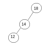
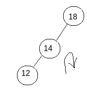
So right rotation need to be performed as shown in the image.
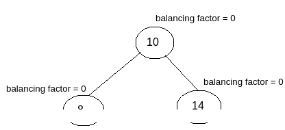
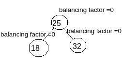
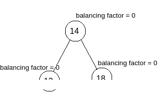
After performing Right Rotation the tree will look like the tree shown in the image. As you can see after performing the Right Rotation , Balancing factor of all the nodes have become proper ( as per the AVL Tree Balancing Rule.).
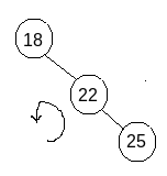
Rotation for the relation RL : For RL relation as a first step we need to perform Right Rotation with respect to the immediate child node of the affected node. As a final step we need to perform Left Rotation with respect to affected node.
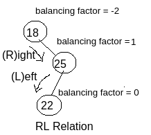
As you can see in the image, RL relation is found so we need to perform Right Rotation with respect to the affected node for giving the intermediate solution.
So as a first step right rotation need to be performed with respect to the immediate child node of the affected node as shown in the image.
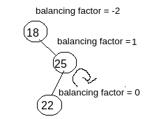
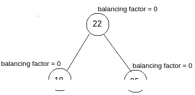
So after performing the first step means right rotation with respect to the immediate child node of the affected node, the intermediate solution will look like as shown in the image.
Then We need to perform the final step means left rotation with respect to the affected node as shown in the image.
Then after performing the final step means left rotation with respect to the affected node, the final solution will look like as shown in the image.
Rotation for the relation LR : For LR relation as a first step we need to perform Left Rotation with respect to the immediate child node of the affected node. As a final step we need to perform Right Rotation with respect to affected node.
As you can see in the image, LR relation is found so we need to perform Left Rotation with respect to the affected node for giving the intermediate solution.
So as a first step left rotation need to be performed with respect to the immediate child node of the affected node as shown in the image.
So after performing the first step means left rotation with respect to the immediate child node of the affected node, the intermediate solution will look like as shown in the image.
Then We need to perform the final step means right rotation with respect to the affected node as shown in the image.
Then after performing the final step means right rotation with respect to the affected node, the final solution will look like as shown in the image.
After detecting proper rotation and giving the solution depending upon the rotation we are going to get a balanced binary search tree. That will follow all the rules and calculations properly. But still there are several special cases where you have to take decision as per the situations. Here we are going to discuss one special case.
Special Case:
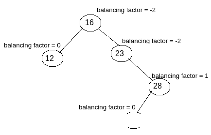
If you find a case where multiple nodes are imbalanced then you should solve the imbalance state of the immediate imbalance node of the just inserted new node.
As you can see in the image there are 2 nodes which are affected, the node with value 16 and the node with value 23. Now you should solve the imbalance state of the node with the value 23 first. As it is the immediate node from the just inserted node with the value 26. So after solving this the complete tree will be automatically balanced.
Few things to be kept in mind for finally checking the result :
After performing all the required rotations you should check whether the result is perfect or not. for checking you should follow the below steps:
- Balancing factor of all the nodes must be calculated after each new node insertion.
- After completion of the AVL Tree procedure , you need to finally check the balancing factor and along with the inorder traversal. If in the Inorder traversal all the elements are found in ascending order means and balancing factors of all the nodes are within allowed range then the AVL Tree is said to be successful.
For Such more codes click here and for video tutorial click here.


